Computer Network Fundamentals
Note: This is all preliminary understanding, not in-depth. Will discuss more when we get to computer networks. # Basic Concepts ## Endpoints and Sessions An endpoint refers to a device on the network that can send or receive data. Communication between two endpoints is called a conversation. ## IP Address 32-bit binary number, commonly represented in dotted decimal notation, changes as devices connect to different local area networks. Part consists of network number, another part is host number, determined by subnet mask. ## Subnet Mask 32-bit binary number, in the form of 1111…0000. Performing AND operation with IP address directly gives the network number, performing AND operation with inverted mask and IP address gives the host number. ## MAC Address 48-bit binary number Unique identifier for each host (constant after leaving factory), physical address of network card, has mapping relationship with IP address in local area network. Network card directly determines whether to send to operating system by comparing the target MAC address in data packets.
The relationship between IP and MAC is similar to mailing address and ID number - mailing address may change, but ID number never changes.
Question: Why do we need MAC addresses when we have IP addresses?
IP address is equivalent to the recipient address on a package. The courier connects a line from origin to destination through the recipient address, then delivers the package to the recipient through logistics transfers between different regions. MAC address is equivalent to the recipient name on a package. MAC address exists more for confirming the other party’s information. Just like when a package crosses several cities to reach you, the courier needs to confirm with you whether the recipient is correct before handing over the package. For example, students in the same class (abstracted as local area network) all know each other, so communication doesn’t need to rely on student numbers (abstracted as IP address here), just call names (MAC address) directly.
Although there are IP addresses, they don’t work in local area networks because ARP protocol (Address Resolution Protocol) is used for network addressing, and in local area networks all hosts are visible to each other. (Besides, IP addresses in local area networks are at most used as criteria for hosts receiving packets to determine whether they are the target host when unpacking during ARP broadcasts, thus choosing whether to respond to ARP replies).
Gateway
A gateway is a “gateway” that connects one network to another network. It’s a network checkpoint. Examples include switches and routers. Gateway is also called network connector and protocol converter. Default gateway implements network interconnection above the network layer, it’s the most complex network interconnection device, only used for interconnecting networks with different high-level protocols. Gateway structure is similar to routers, the difference is the interconnection layer. Gateways can be used for both WAN and LAN interconnection.
==Note: Due to historical reasons, many TCP/IP literature used to call routers used at the network layer as gateways. Today many local area networks use routers for network access, so gateway usually refers to the router’s IP== ## TCP and UDP ### UDP Internet protocol suite supports a connectionless transport protocol called User Datagram Protocol (UDP). UDP provides applications with a method to send encapsulated IP data packets without establishing a connection. RFC 768 describes UDP. Internet transport layer has two main protocols that complement each other. The connectionless one is UDP, which does almost nothing special except providing applications with data packet sending functionality and allowing them to structure their own protocols at required levels. The connection-oriented one is TCP, which does almost everything.
TCP (More powerful but also more difficult)
Transmission Control Protocol (TCP) is a connection-oriented, reliable, byte-stream-based transport layer communication protocol, defined by IETF RFC 793. TCP is designed to adapt to layered protocol hierarchies that support multi-network applications. Paired processes in host computers connected to different but interconnected computer communication networks rely on TCP to provide reliable communication services. TCP assumes it can obtain simple, possibly unreliable datagram services from lower-level protocols. In principle, TCP should be able to operate over various communication systems from hard-wired connections to packet-switched or circuit-switched networks.
Connection Establishment and Termination
Connection Establishment: 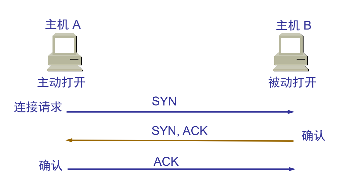 Connection Termination:
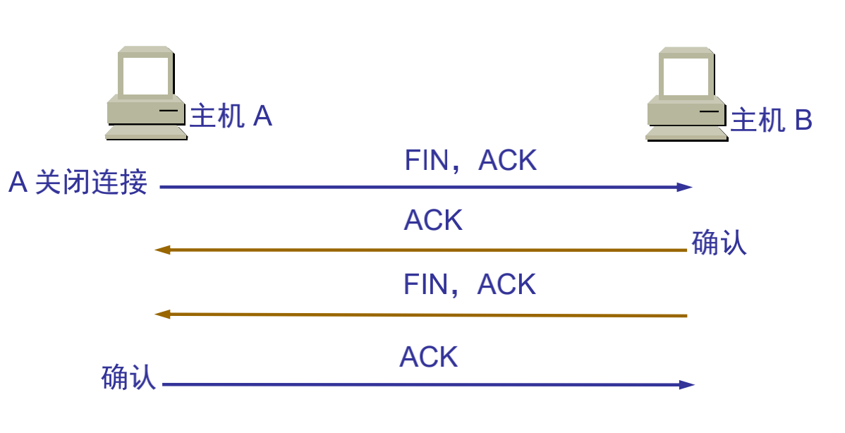
Main Features
TCP is a wide area network-oriented communication protocol designed to provide a communication method between two communication endpoints with the following characteristics when communicating across multiple networks: * Stream-based approach; * Connection-oriented; * Reliable communication method; * Minimize system bandwidth overhead due to retransmission when network conditions are poor; * Communication connection maintenance is oriented to the two endpoints of communication, without considering intermediate network segments and nodes.
To meet these characteristics of the TCP protocol, TCP protocol makes the following provisions: ①Data fragmentation: Fragment user data at the sender, reassemble at the receiver, TCP determines fragment size and controls fragmentation and reassembly; ②Arrival confirmation: When the receiver receives fragmented data, send a confirmation to the sender based on the fragment data sequence number; ③Timeout retransmission: The sender starts a timeout timer when sending fragments, if no corresponding confirmation is received after the timer expires, retransmit the fragment; ④Sliding window: The receive buffer space size of each party in a TCP connection is fixed, the receiver only allows the other end to send data that the receiver buffer can accommodate, TCP provides flow control based on sliding window to prevent faster hosts from causing buffer overflow in slower hosts; ⑤Out-of-order handling: TCP fragments transmitted as IP datagrams may arrive out of order, TCP will reorder the received data and deliver the received data to the application layer in the correct order; ⑥Duplicate handling: TCP fragments transmitted as IP datagrams will have duplicates, the TCP receiver must discard duplicate data; ⑦Data checksum: TCP maintains checksums of its header and data, this is an end-to-end checksum designed to detect any changes in data during transmission. If the checksum of a received fragment has errors, TCP will discard this fragment and not confirm receipt of this segment, causing the peer to timeout and retransmit.
Simple Distinction
Internet transport layer has two main protocols that complement each other. The connectionless one is UDP, which does almost nothing special except providing applications with data packet sending functionality and allowing them to structure their own protocols at required levels. The connection-oriented one is TCP, which does almost everything.
DHCP Service
DHCP Introduction
DHCP (Dynamic Host Configuration Protocol) is a local area network protocol. It refers to a server controlling a range of IP addresses, where client machines can automatically obtain server-assigned IP addresses and subnet masks when logging into the server. Usually applied in large local area network environments, its main function is to centrally manage and allocate IP addresses, enabling hosts in the network environment to dynamically obtain IP addresses, Gateway addresses, DNS server addresses and other information, and improve address utilization.
DHCP protocol uses a client/server model, where dynamic host address allocation tasks are driven by network hosts. When the DHCP server receives address application information from network hosts, it sends relevant address configuration information to network hosts to achieve dynamic configuration of network host address information.
DHCP Functions
DHCP has the following functions: 1. Ensure that any IP address can only be used by one DHCP client at the same time. 2. DHCP should be able to assign permanent fixed IP addresses to users. 3. DHCP should be able to coexist with hosts that obtain IP addresses by other methods (such as hosts with manually configured IP addresses). 4. DHCP servers should provide services to existing BOOTP clients.
Address Allocation Methods
DHCP has three mechanisms for allocating IP addresses: 1) Automatic Allocation: DHCP server assigns a permanent IP address to the host. Once the DHCP client successfully leases an IP address from the DHCP server for the first time, it can use that address permanently. 2) Dynamic Allocation: DHCP server assigns a time-limited IP address to the host. When the time expires or the host explicitly abandons the address, the address can be used by other hosts. 3) Manual Allocation: The client’s IP address is specified by the network administrator, and the DHCP server only tells the client host the specified IP address. Among the three address allocation methods, only dynamic allocation can reuse addresses that clients no longer need.
FTP
FTP Introduction
File Transfer Protocol (FTP) is a set of standard protocols for file transfer over networks. It works at the seventh layer of the OSI model, the fourth layer of the TCP model, i.e., the application layer, using TCP transmission instead of UDP. Clients must go through a “three-way handshake” process before establishing a connection with the server, ensuring that the connection between client and server is reliable, and it’s connection-oriented, providing reliable guarantee for data transmission. FTP allows users to communicate with another host through file operations (such as file addition, deletion, modification, query, transfer, etc.). However, users don’t actually log into the computer they want to access to become full users. FTP programs can be used to access remote resources, implement user round-trip file transfer, directory management, and email access, etc., even if both computers may have different operating systems and file storage methods. ### Transmission Methods FTP has two transmission methods: ASCII and binary. #### ASCII Transmission Method Assuming the file being copied contains simple ASCII text, if the remote machine is not running UNIX, ftp usually automatically adjusts the file content during file transfer to interpret the file in the format that the other computer stores text files. But often there are cases where the file being transmitted doesn’t contain text files, they might be programs, databases, word processing files, or compressed files. Before copying any non-text files, use the binary command to tell ftp to copy character by character. #### Binary Transmission Mode In binary transmission, the bit order of the file is preserved so that the original and copy are bit-by-bit corresponding. Even if the file containing the bit sequence on the destination machine is meaningless. For example, Macintosh transmits executable files to Windows systems in binary mode, and this file cannot be executed on the other system. If binary files are transmitted in ASCII mode, translation will still occur even if not needed. This will corrupt data. (ASCII mode generally assumes the first significant bit of each character is meaningless because ASCII character combinations don’t use it. If transmitting binary files, all bits are important.)
FTP Supports Two Modes
FTP client initiates FTP session and establishes corresponding connection with FTP server. During FTP session, two connections need to be established: control information process and data process. Control connection cannot complete data transmission tasks, only used to transmit internal commands executed by FTP and command responses and other control information; data connection is the connection for file transmission between server and client, it’s full-duplex, allowing simultaneous bidirectional data transmission. When data transmission is complete, the data connection is revoked, returning to FTP session state until the control connection is revoked and the session exits. FTP supports two modes: Standard (PORT mode, active mode), Passive (PASV, passive mode). #### Port Mode (Active Mode) FTP client first establishes connection with server’s TCP port 21 for sending commands. When the client needs to receive data, it sends PORT command on this channel. PORT command contains which port the client uses to receive data. When transmitting data, the server connects to the client’s specified port through its own TCP port 20 to send data. FTP server must establish a new connection with the client for data transmission. #### Passive Mode Control channel establishment is similar to Standard mode, but sends Pasv command after establishing connection. After the server receives the Pasv command, it opens a temporary port (port number greater than 1023 and less than 65535) and notifies the client of the request to transmit data on this port. The client connects to this port of the FTP server, then the FTP server transmits data through this port.
Note
Many firewalls are configured to not allow external connections, so many FTP servers behind firewalls or on internal networks don’t support PASV mode because clients cannot open high ports of FTP servers through firewalls; while many internal network clients cannot use PORT mode to log into FTP servers because TCP 20 from the server cannot establish a new connection with clients on the internal network, causing it to not work. ## HTTP Hyper Text Transfer Protocol (HTTP) is a simple request-response protocol that usually runs on top of TCP. Request and response message headers are given in ASCII form. ### Application Scenarios When HTTP was first born, it was mainly used for WEB content retrieval. At that time, content wasn’t as rich as it is now, layout wasn’t as beautiful, and user interaction scenarios were almost non-existent. For this simple scenario of retrieving web content, HTTP performed quite well. But with the development of the internet and the birth of WEB2.0, more content began to be displayed (more image files), layout became more beautiful (more CSS), and more complex interactions were introduced (more JS). The total amount of data loaded and the number of requests when users open a website homepage are also constantly increasing. ### Message Format HTTP messages consist of requests from client to server and responses from server to client.
Request Message
Request message format is as follows:
Request line - General information header - Request header - Entity header - Message body
Request line starts with method field, followed by URL field and HTTP protocol version field, ending with CRLF. SP is the separator. Except for CF and LF being required in the final CRLF sequence, others are optional. For specific content about general information headers, request headers, and entity headers, refer to related documents.
Response Message
Response message format is as follows:
Status line - General information header - Response header - Entity header - Message body
Status code consists of 3 digits, indicating whether the request was understood or satisfied. Reason analysis is a brief description of the original status code. Status codes are used to support automatic operations, while reason analysis is for user use. Clients don’t need to check or display syntax. For specific content about general information headers, response headers, and entity headers, refer to related documents.
Detailed HTTP Message Explanation Click Here ### Status Codes After the server receives an HTTP request, it sends response information to the client, placed in the first line. The most important part is the status code
1 | HTTP/1.1 200 OK |
Status Code Types - First Digit
- 1**: Request successfully received, continue processing; range 100~101
- 2**: Server successfully processed request; range 200~206
- 3**: Accessed resource was moved, inform client to resend new request; range 300~305
- 4**: Client error, server cannot process request, such as accessed resource doesn’t exist; range 400~415
- 5**: Server error; range 500~505
Common HTTP Status Codes
- 200: Client request successful (common)
- 302: Redirect
- 404: Requested resource doesn’t exist (common)
- 400: Client request syntax error, cannot be understood by server
- 401: Access unauthorized
- 403: Server received request but refused service
- 500: Server internal error (common)
- 503: Server currently cannot process, may be able to after some time
For specific details, see “Illustrated HTTP”
Communication
Internal Network Communication (Local Area Network)
Ethernet
Ethernet is a computer local area network technology.
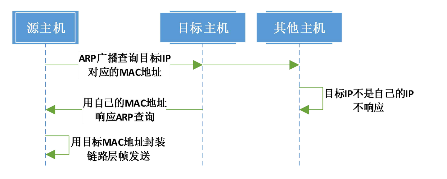
Internal Network Communication Process
The internal network mentioned here generally refers to Local Area Network (LAN). When we say two terminals are in the same internal network, it essentially means the network numbers of the two terminals are the same. If two terminals are in the same internal network, their communication method is as follows
ARP Introduction
ARP Protocol
Address Resolution Protocol (ARP) is a TCP/IP protocol for obtaining physical addresses based on IP addresses. When a host sends information, it broadcasts ARP requests containing the target IP address to all hosts on the local area network and receives return messages to determine the target’s physical address; after receiving return messages, it stores the IP address and physical address in the local ARP cache and retains them for a certain time, directly querying the ARP cache for the next request to save resources. Address Resolution Protocol is based on mutual trust between hosts in the network. Hosts on the local area network can autonomously send ARP reply messages, and other hosts will record them in the local ARP cache without detecting the authenticity of the reply messages when received; thus attackers can send fake ARP reply messages to a certain host, making the information sent unable to reach the expected host or reach the wrong host, constituting ARP spoofing. ARP commands can be used to query the correspondence between IP addresses and MAC addresses in the local ARP cache, add or delete static correspondences, etc. Related protocols include RARP and proxy ARP. NDP is used to replace Address Resolution Protocol in IPv6.
ARP Spoofing
ARP spoofing, also known as ARP poisoning (often translated as ARP virus on the network) or ARP attack, is an attack technique targeting the Ethernet Address Resolution Protocol (ARP). By spoofing the gateway MAC address of visitor PCs in the local area network, it makes visitor PCs mistakenly think that the attacker’s changed MAC address is the gateway’s MAC, causing network failure. This attack allows attackers to obtain data packets on the local area network and even tamper with data packets, and can make specific computers or all computers on the network unable to connect normally.
Free ARP
- Check for address conflicts
- Update own ARP cache
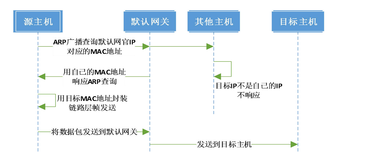
Internet Communication Process
If the host is on the Internet, the target address and source address are not in the same internal network, meaning the network number parts of their IP addresses are not consistent. At this time, data packets need to be sent to the “default gateway” for routing. The specific communication process is as follows: